http://wowslider.net/ by WOWSlider.com v8.7
- Tilt Sensor (TS-HE-P) is a tilt sensing product based on hall effect technology and Pendulum principle with a damping control.
- TS-HE-P is built on mechanism with high reliabilit and strong construction for highly rugged environment. Since the Product is based on Contactless Hall's effect Technology it has very long life
- The Output signal correspondence to 0 to 360deg of tilt. This full range is programmable based on requirement.
- Since the Product is based on Contactless Hall's effect Technology it has very long life, No effect of radial load upto certain extent, High vibration withstanding rating.
- Tilt sensor can be specially programmed to have 4,3 or 2 cycles in over revolution hence increasing the accuracy.
- For modern microcontrollers TS-HE-P is capable to give output in 0 to 3.3Vdc and to suppress the effect of Noise PWM output version is available.
- TS-HE-P is a ideal product for application such as hospital beds, crane boom angle and SPM machine builders.
VARIANTS
- 12 bit resolution 24 or 5Vinput and 0 to 3.3Vdc/5Vdc/10Vdc/4 to 20mA/0 to 20mA Analog Output.
- 24 or 5 or 3.3Vinput and Redundant (Dual) Output 0 to 5Vdc.
- 24 or 5 or 3.3Vinput and PWM Output..
- 14 bit resolution 24 or 5 or 3.3Vinput and SPI along with PWM Output. 24 or 5 or 3.3Vinput and I2C along with PWM Output.
- Connectors or shielded cable available.
- IP 69k Protection available.
BENEFITS
- Non Contact Rotary Position Sensor based on Hall Effect Tenology.
- Accurate Linearity upto 1% F.S. or 0.5% F.S (on request)
- Extremely Long Life.
- Extremely Compact in Size.
- Angle programmable based on customer specific requirement.
- Short Circuit Protected. ( For 5Vdc and PWM output versions).li>
- Overvoltage protected. ( For 5Vdc and PWM output versions).
Mounting
3 M3 Threaded holes at a PCD of 38mm dia at 120deg apart Along with 1 at 60deg apart from other two M3 threaded holes .
The hole in the panel should not be more than 9.5mm. It is recommended to Ground the shielding of the Shielded cable in order to gaurd the sensor from surges or environmental
Environment
| Parameter | Value |
|---|---|
| Operating Temperature | -40 to 75 deg (standard) -40 to 140 deg ( on request) |
| Storage Temperature | -40 to 75 degC |
| Vibration | 20g |

Mechanical characteristics

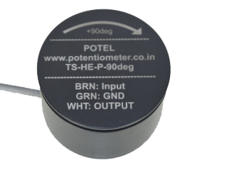
- TS-HE-P has been calibrated to have 2.5Vdc (50% of F.S output) output subject to 5Vdc supply when it is being mounted perpendicular to the gravity .
- TS-HE-Pgives 2.5Vdc to 5Vdc and 2.5Vdc to 0Vdc when the Sensor is tilted in +/- direction to the Axis of the Sensor respectively.
| Screw Connector | Shielded Cable | |
|---|---|---|
| Vsupply | Pin 1 | Brown |
| Ground | Pin 2 | Green |
| Voutput | pin 3 | White |

| Parameter | Results |
|---|---|
| Supply Voltage (Vsupply) | 5Vdc(+/- 10%) or 6-35Vdc or 24Vdc |
| Supply Current | 20mA // 50mA // 100mA |
| Response time | 50mS |
| Resolution | 12bit |
| Load Resistance | Minimum 10k ohms |
| Output (Voutput) | 3 % to 97% Vsupply (Ratiomatric) for 5Vdc Input 0.5Vdc to 4.5Vdc for 6-35Vdc Input |
| Linearity | 1% Independent Linearity(Available 0.5% on request) |

| Parameter | Results |
|---|---|
| Supply Voltage (Vsupply) | 5Vdc(+/- 10%) or 3.3Vdc |
| Supply Current | 20mA |
| Frequency | 200Hz, 500Hz, 1K Hz or 2 Khz based on requirement |
| Resolution | 12bit |
| Output (Voutput) | 0% to 100% duty Cycle |
| Linearity | 1% Independent Linearity ( Available 0.5% on request) |
Redundant Analog Output

| Parameter | Results |
|---|---|
| Supply Voltage (Vsupply) | 6 to 35Vdc |
| Supply Current | 50mA |
| Frequency | 20Hz |
| Resolution | 12bit |
| Output (Voutput) | 0 to 5Vdc ( Output1 and Output 2 will have a phase difference of 180deg) |
| Load Resistance | Minimum 10K Ohms |
| Linearity | 1% Independent Linearity(Available 0.5% on request) |
Incremental Output

| Parameter | Results |
|---|---|
| Supply Voltage (Vsupply) | 5Vdc / 3.3Vdc |
| Supply Current | 20mA |
| Incremental Output | |
| Electrical Speed | 10000RPM Max. |
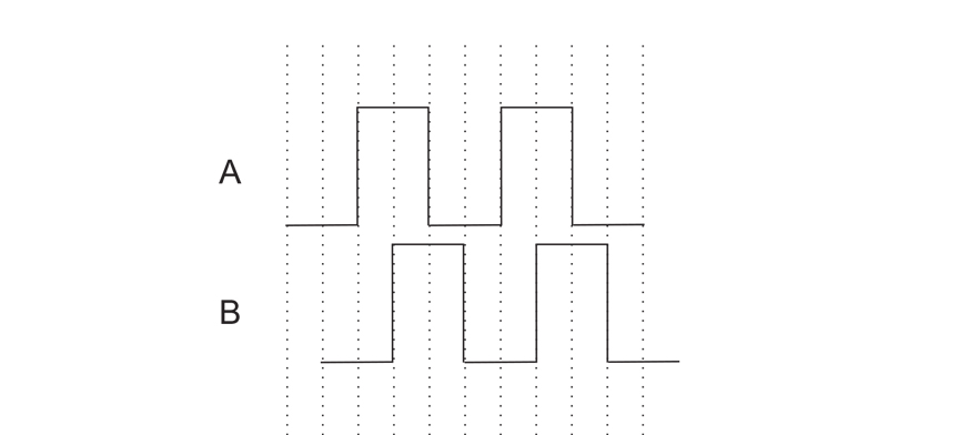
| PPR (Pulse Per Revolution)(A&B) | 25,50,100,200,256,300,400,500,512,1000,1024 A & B Pulse Lag each other by 90deg.(TTL) |
| Output (Voutput) | 0 to 5Vdc ( Redundant Output) (ideally 3% to 97% Vinput) |
| Index pulse Z | 1 pulse per RPM (TTL) |
Low Speed Quadrature Output
| Parameter | Results |
|---|---|
| Supply Voltage (Vsupply) | 5Vdc / 3.3Vdc |
| Supply Current | 20mA |
| Incremental Output | |
| Electrical Speed | 400RPM Max. |
| PPR (Pulse Per Revolution)(A&B) | 8,16,32,64,128,256,512,1024,2048 A & B Pulse Lag each other by 90deg.(TTL) |
| Output (Voutput) | 0 to 5Vdc ( Redundant Output) (ideally 3% to 97% Vinput) |
| Index pulse Z | 1 pulse per RPM (TTL) |
- The TS-HE-P is a Tilt sensor which acts as a slave and communicate with master micro controller as per the standard Protocol ofSPI.
- TS-HE-P communicate in 16 Bit of Transmission.
- As per standard protocol of SPI TS-HE-P communicate with master protocol when the MOSI pin is active high or 3FFF hex data is sent on the bus and the CS pin need to toggle from low to high for only one clock pulse.
- After each cycle of communication it is compulsory to toggle CS pin from high to low.
- TS-HE-P has a provision of Dual Output first SPI communication and PWM mode of communication 14 Bit and 12 Bit of Resolution respectively.
- Number of sensors can be connected in daisy chain mode of 4 wire or (n+3 wire connection). please contact Mr. Pavan Kinariwala (pavankinariwala@gmail.com) for more information on the same.

| Parameter | Results |
|---|---|
| Input Voltage (Vinp) | 5Vdc / 3.3Vdc |
| Maximum clock Frequency | 50k Hz. |
| Digital pin Input / output level including address pins. VDD- 5Vdc (Vinp --> 5Vdc) VDD- 3.3Vdc (Vinp --> 3.3Vdc) |
1 --> VDD (5V or 3.3V) -0.7V 0 --> GND +0.4V |
| PMW Frequency | 1 Khz |
- The TS-HE-P is a Tilt sensor which acts as a slave and communicate with master micro controller as per the standard Protocol of I2C. It is also known as Two Wire Communication.
- TS-HE-P communicate in 8 Bit of Transmission.
- As per standard Protocol each slave (TS-HE-P) has a Slave address of 7 bit which is being made of two Address Pin 1 and 2 while the remaining 4 bits are always 0 and MSB being 1. Address pin 1 and 2 are Least significant bit of Address. Hence we can use maximum of 4 such sensors in a Daisy chain mode of communication with slave address as 1000001 / 1000000 / 1000011 / 1000010.
- TS-HE-P has a provision of Dual Output first I2C communication and PWM mode of communication 14 Bit and 12 Bit of Resolution respectively.
- TS-HE-P communicates the angle information in two cycles. By sending the register address 254 and 255. To have the complete angle information we need to eliminate two most significant bit (6 and 7) of the data byte we receive after sending register address 255.

| Parameter | Results |
|---|---|
| Input Voltage (Vinp) | 5Vdc / 3.3Vdc |
| Maximum clock Frequency | 10k Hz. |
| Digital pin Input / output level including address pins. VDD- 5Vdc (Vinp --> 6 to 35Vdc or 5Vdc) |
1 --> VDD (5V or 3.3V) -0.7V 0 --> GND +0.4V |
| PMW Frequency | 1 Khz |
For Any technical Information on TS-HE-P Kindly drop a email on info.potentiometer@gmail.com

Standard 6.3mm shaft dia

Ball Bearing version with 3mm shaft dia

Ball Bearing Servo Mount version with 3mm shaft dia
